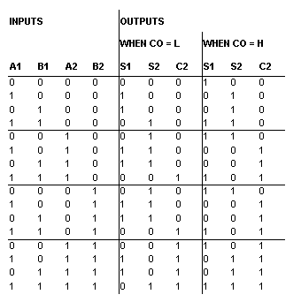
3 bit binary adder truth table
Half Adder and Full Adder circuits is explained with their truth tables in this article. Design of Full Adder using Half Adder circuit is also shown.
Single-bit Full Adder circuit and Multi-bit addition using Full Adder is also shown. Before going into this subject, it is very important to know about Boolean Logic and Logic Gates. With the help of half adder, we can design circuits that are capable of performing simple addition with the help of logic gates. These are the least possible single-bit combinations. Though this problem can be solved with the help of an EXOR Gate, if you do care about the output, the sum result must be re-written as a 2-bit output.
The result is shown in a truth-table below. Take a look at the implementation below. For complex addition, there may be cases when you have to add two 8-bit bytes together.
This can be done only with the help of full-adder logic. This type of adder is a little more difficult to implement than a half-adder. The main difference between a half-adder and a full-adder is that the full-adder has three inputs and two outputs. The first two inputs are A and B and the third input is an input carry designated as CIN. When a full adder logic is designed we will be able to string eight of them together to create a byte-wide adder and cascade the carry bit from one adder to the next.
The Full-Adder
The output carry is designated as COUT and the normal output is designated as S. Take a look at the truth-table. From the above truth-table, the full adder logic can be implemented. We can see that the output S is an EXOR between the input A and the half-adder SUM output with B and CIN inputs. We must also note that the COUT will only be true if any of the two inputs out of the three are HIGH. Thus, we can implement a full adder circuit with the help of two half adder circuits.
The first will half adder will basics on stock market used to add A and B to produce a partial Sum. The second half adder logic can be used to add CIN to the Sum produced by the first half adder to get the final S output. If any of the half adder logic produces a carry, there will be an output carry.
Binary Arithmetic Circuits
Thus, COUT will be an OR mds coordinator work from home of the half-adder Carry outputs. Take a look at the implementation of the full adder circuit shown below.
Though the implementation of larger logic diagrams is possible with the above full adder logic a simpler symbol is mostly used to represent the operation. Given below is a simpler schematic 3 bit binary adder truth table of a one-bit full adder.
With this type of symbol, we can add two bits together taking a carry from the next lower order of magnitude, and sending a carry to the next higher order of magnitude.
SINEPE-NPR » Erro - Página não encontrada
In a computer, for a multi-bit operation, each bit must be represented by a 3 bit binary adder truth table adder and must be added simultaneously. Thus, to add two 8-bit numbers, you will need 8 full adders which can be formed by cascading two of the 4-bit blocks. The addition of two 4-bit numbers is shown below. Hi Mounika say you have four full adders you can make a 4 digit display that is from 0 to Due to this half adder additon say to a 3 digit meter with a measuring range of is increased 0 to Hi newbie in http: Your email address will not be published.
Home Buy Project Kits Store Advertise With Us Write For Us. Just type and press 'enter'. Half Adder and Full Adder john February 10, 34 Comments. Half Adder and Full Adder Circuit Half Adder and Full Adder circuits is explained with their truth tables in this article. BOOLEAN LOGIC TAKE A LOOK: LOGIC GATES TAKE A LOOK: FLIP FLOPS Half Adder With the help of half adder, we can design circuits that are capable of performing simple addition with the help of logic gates.

Let us first take a look at the addition of single bits. Multi-Bit Addition using Full Adder. Previous post Next post.
You may also like: Pulse Width Modulation — What is it? Half adder Ripple carry adder Flip Flop Conversion Implement Logic Gates. Class A Power Amplifier - Tutorial with Design and Theory 2 X 22 Watt Stereo Amplifier using IC TDA PWM inverter circuit PROCEDURE TO USE MPLAB SIM LM35 and Arduino - Temperature Measurement and Display on LCD. Engr Shahkaz Khalid Butt. The demonstration is Crystal clear! How to make full adder circuit using two half adder circuit.
Nice Sir,very simple and clear explanation. NOT FULFILLED WITH THE RESULT.
Awesome n easy explanation. Thanks sir for simple and clear explanation. Thank u very much the article is a very 9c 1. Thanks a lot sir for your helpful information. Very clear and understandable. Leave a Reply Cancel reply Your email address will not be published.

Get Daily Updates via Email. Latest Articles Timer Circuits in Proteus How to Use ADC Analog to Digital Converter in AVR — Atmega32 Op Amp circuits in Proteus How a Thermostat Works — Tutorial 10 Things to Consider While choosing a PCB Prototype Service DIY SwitchBoard for Home Automation Robot using Arduino and Bluetooth Module Obstacle Avoidance Robot Transistor Circuits in Proteus Arduino Irrigation and Plant Watering using Soil Moisture Sensor Home Automation using Arduino and GSM Module.
Like Us on Facebook. Pages About Advertise With Us Authors Buy Project Kits Datasheets Disclaimer Electronic Circuit Symbols Lab Manuals Electronic Circuits Lab Microcontroller lab Microprocessor Lab Privacy Policy Resistor Color Code Calculator Sitemap Testing Components Write For Us.
About Privacy Policy Write For Us Earn Money.
